Tuesday 30 April 2013

TANCET Counselling Schedule 2013 for MBA , MCA , ME / MTech Admissions


TANCET Counselling Schedule 2013 for MBA , MCA , ME / MTech Admissions

TANCET 2013 Counselling Tancet examination was held on April 6th & 7th for Post Graduate Admissions into following degrees , MBA , MCA , ME , MTech courses at various exam centres across the state . Students who got scored the maximum marks will be able to choose their stream and college of pursuing the [...]

The post TANCET Counselling Schedule 2013 for MBA , MCA , ME / MTech Admissions appeared first on Anna University.

Anna University May / June 2013 Results for 2nd, 4th, 6th, 8th Sem


Anna University May / June 2013 Results for 2nd, 4th, 6th, 8th Sem

Anna University Result 2013 Anna University conducts examination for even semester academics , students who are pursuing 2nd semester, 4th semester, 6th semester & 8th semester are announced the Exam schedule which begins from May 8th 2013 . Anna Univ Result for May/June 2013 will released first for 8th Semester or final sem students which [...]

The post Anna University May / June 2013 Results for 2nd, 4th, 6th, 8th Sem appeared first on Anna University.

Anna University May / June 2013 Results for 2nd, 4th, 6th, 8th Sem


Anna University May / June 2013 Results for 2nd, 4th, 6th, 8th Sem

Anna University Result 2013 Anna University conducts examination for even semester academics , students who are pursuing 2nd semester, 4th semester, 6th semester & 8th semester are announced the Exam schedule which begins from May 8th 2013 . Anna Univ Result for May/June 2013 will released first for 8th Semester or final sem students which [...]

The post Anna University May / June 2013 Results for 2nd, 4th, 6th, 8th Sem appeared first on Anna University.

Monday 29 April 2013

CS2351 Artificial Intelligence Important Questions for May June 2013 Exam


CS2351 Artificial Intelligence Important Questions for May June 2013 Exam

Anna University

Department of Computer Science Engineering

Semester : 6
Department : CSE
Subject Code : CS2351
Subject Name : Artificial Intelligence


Unit 1

1) Explain in detail about Agents and their types.

2) Explain in detail about uninformed search strategies with example.

3) Explain in detail about informed search strategies with example.

4) Explain in detail about Constraint satisfaction problem with example.


Unit 2

1. Explain in detail about forward & backward chaining algorithm with example.

2. Explain in detail about First order Logic & Inferences in First Order Logic with example.

3. Explain in detail about logical agents with example.

4. Explain in detail about Resolution & Resolution inference Rule with example.

5. Explain with at least 4 examples for PEAS cycle.


Unit 3

1. Explain about partial order planning with an example.

2. Explain about the different types of state space searches.

3. Explain about partial order planning algorithm.

4. Describe in detail about planning graphs.

5. Explain in detail about graph plan algorithm.

6. Explain in detail about conditional planning with an example.

7. Explain about replanning agent algorithm.


Unit 4

1. Explain in detail about Bayesian networks with an example.

2. Explain in detail about conditional probability.

3. Explain in detail about Markov Process with example.

4. Explain in detail about dynamic Bayesian networks.

5. Explain in detail about hidden markov models with example.

6. Explain in detail about inference in Bayesian network.


Unit 5

1. Explain the learning decision tree with algorithm with example.

2. (i).Explain the explanation based learning?

(ii).Explain how learning with complete data is achieved?

3. Discuss learning with hidden variables?

4. Explain all the statistical learning method with example.

5. Explain in detail about Reinforcement learning.


Sunday 28 April 2013

Anna University Examinations May / June Important Questions 2013 Anna univ Important Questions


Anna University Examinations May / June Important Questions 2013 Anna univ Important Questions

Anna University Examinations May / June Important Questions 2013 - Anna Univ Important Questions

Anna University Important Questions For May June 2013 Exams, this Will be the Most Aspiring Search throughout May and June 2013 Month

History of Anna Univ Important Questions ? Who initiated ?

Full Credits Goes To rejinpaul.com For initiating " Important Questions " In the Year 2011 For Anna Univ Students 

We are the pioneer In Providing Important Questions For Anna University Exams For All Engineering Students From the year 2011 [ (i.e) Our First Post Regarding Important Questions Is On 03/11/2011 For Nov/Dec 2011 Anna Univ Examinations ], After Some sort of days Many Websites Copied, Followed rejinpaul.com and provided the same For students ,  We Are proud and Happy to Hear that When Students Pronounce  Like 

" Anna University rejinpaul "
" rejinpaul Important Questions "


We Continuously Monitor Anna university Students need and we will react Accordingly , We Are Happy To Announce That Our team Working On May / June 2013 Anna Univ Exam Important Questions , Same Will be Posted Instantly In rejinpaul.com , So keep Watching Us

We Plan To Start Publish Important Questions by First Week  May 2013

Share with your friends on facebook, twitter, google + 

Anna University Students Search Query

  • Important Questions For 4th Sem Exams
  • Anna Univ Important Questions For 6th Sem 
  • Anna University 8th Semester Important Questions

Principles Of Communication Question Paper for Anna Univ IT Department


Principles Of Communication Question Paper for Anna Univ IT Department


B.E./B.Tech. DEGREE EXAMINATION, NOVEMBER/DECEMBER 2009 
Third Semester 
Information Technology 
IT 2202 — PRINCIPLES OF COMMUNICATION 
(Regulation 2008) 
Time : Three hours Maximum : 100 Marks 
Answer ALL Questions 
PART A — (10 × 2 = 20 Marks) 
1. Define amplitude modulation. 
2. What is modulation index? 
3. Why is ASK called as ON-OFF keying? 
4. What are the differences between QASK and QPSK? 
5. Define sampling rate? 
6. What is ISI? 
7. Define Pseudonoise sequence? 
8. What are the different types of multiple access techniques? 
9. Define Kepler's three laws of planetary motions. 
10. What are the losses encountered by optical fiber? 

PART B — (5 × 16 = 80 Marks) 

11. (a) (i) Write short notes on : 
 (1) AM voltage distribution. (4) 
 (2) AM power distribution. (4) 
 (ii) An audio frequency signal 10 sin 2π ×500t is used to amplitude 
modulate a carrier of 50 t sin 2π ×10 . Calculate 
 (1) Modulation index (2) 
 (2) Side band frequencies (2) 
 (3) BW required (2) 
 (4) Total power delivered to the load of 600 Ω. (2) 
Or 
(b) (i) Compare FM and AM. (12) 
 (ii) The phase deviation constant in a phase modulation system is 
K = 0.01 rad/v. Calculate the maximum phase deviation when a 
modulating signal of 10 V is applied? (4) 
12. (a) (i) Explain the principle of FSK transmitter and receiver. (10) 
 (ii) Write short notes on the spectrum and bandwidth of FSK. (6) 
Or 
(b) (i) Compare the various types of digital modulation techniques. (8) 
 (ii) Explain the eyepattern in base band digital transmission with a 
neat diagram. (8) 
13. (a) (i) Explain the elements of PCM system with a neat block diagram. (12) 
 (ii) What is companding? (4) 
Or 
(b) (i) Find the signal amplitude for minimum quantization error in a 
delta modulation system if step size is 1 volt having repetition 
period 1 ms. The information signal operates at 100 Hz. (4) 
 (ii) Describe the operation of DPCM system with a relevant diagram.(12) 
14. (a) (i) Write a short note on frequency hop spread spectrum. (10) 
 (ii) Explain the applications of spread spectrum techniques. (6) 
Or 
(b) (i) Give a detail account of the different types of multiple access 
techniques. (10) 
 (ii) Compare TDMA and CDMA. (6) 
15. (a) (i) Discuss briefly the basic satellite communication system. (8) 
 (ii) Write short notes on the LEO and GEO orbits. (8) 
Or 
(b) Enumerate the elements of an optical fiber transmission link. (16) 

Anna University Result 2013 for May / June Exams - 4th Sem, 6th Semester, 8th Sem anna univ results


Anna University Result 2013 for May / June Exams - 4th Sem, 6th Semester, 8th Sem anna univ results

Anna University Result 2013 for May / June Exams - 4th Sem, 6th Semester, 8th Sem anna univ results

Anna University Result for May / June 2013 Exams 

Anna University Exams May June 2013 For 2nd sem , 4th semester, 6th Semester, 8th Semester Started On 8th May 2013 and Anna University Exams For April / May / June 2013 Exams Will Complete at the end of May 2013 Month Exam Results For 4th sem, 6th sem and 8th Semester Anna University Affiliated Engineering College Be/BTECH/ME/MTECH students


Anna University May / June 2013 Results

Anna University May/June 2013 Results For BE / Btech UG and PG results are Yet To Announce By Anna University chennai . Anna univ result for 8th semester May /June Exam results Will Be probably Announced before the end of June 2013 month to facilitate students to Join for Jobs, higher studies  

Anna University Chennai, Coimbatore, Madurai , Tirunelveli, Tirchy May / June 2013 Exam results For 8th Semester Will be announced combined

Students Can Check the Below After May June Exam results Has Announced
  • Anna University Examination Results 2013
  • Anna University Results May/June 2013
  • Anna University Results May / June 2013
  • Anna University Results Date for May / June Exams 2013
  • Anna University Results for UG 4th, 6th, 8th Semester Exams
Anna Univ results for May / June 2013 Examination Result announcing date will be displayed here very soon, Stay live for results

Anna University Result 2013 for May / June Exams - 4th Sem, 6th Semester, 8th Sem anna univ results

Incoming Search :


Anna University Results 2013
Anna University Chennai
Anna University Result
Anna University
Anna University Results
Anna University Examination Result

Friday 26 April 2013

Revaluation Result for 1st semester BE / BTech / ME / MTech January 2013 exam - Anna University


Revaluation Result for 1st semester BE / BTech / ME / MTech January 2013 exam - Anna University

Revaluation Result for 1st semester BE / BTech / ME / MTech January 2013 exam  -Anna University results

Anna University Revaluation result 2013

Anna University Students Admitted in the year August 2012 written their 1st semester examination - ( Anna University First Semester Exams  ) In the January 2013 Month - Anna University Exams Result 2013 , Anna University results for First Semester Examination results 2013 Has Been Announced on 24th April 2013 , Students Who Got Failed / Got Low Grades in Anna University First Semester January 2013 UG / PG Exams , Applied For Anna University revaluation Cum Paper Valuation Students are now waiting for Anna University 1st semester revaluation results


Revaluation result for Anna University 1st Sem

Once the Anna Univ reval results 2013 for first semester examination has Been Announced By Anna University , First year Students Who Written First Semester Exam Can Checkout their results here 

  • anna university revaluation result for 1st semester
  • revaluation result for first semester 2013
  • anna univ reval result 2013
  • jan 2013 reval result date
  • revaluation result date
Revaluation result for UG / PG 1st Semester Exams

Students can Checkout their results @ rejinpaul.Com here By Visiting Below Link


Revaluation result for 1st Semester Exams UG / PG 

Strength Of Materials Question Papers ME2254 Anna University Question paper 4th sem mech


Strength Of Materials Question Papers ME2254 Anna University Question paper 4th sem mech


Strength Of Materials Question Papers ME2254 Anna University Question paper 4th semester mechanical Engineering

Students here You Can Find Anna University Question paper for 4th sem mechanical Question Paper - Previous Year , Model question papers for second year mechanical engineering students, Strength Of Materials Question Papers is very important for 4th semester anna university mechanical engg students for their May June 2013 Examination


Strength Of Materials SOM Question Paper Download For 4th sem


University : Anna University

Subject : ME2254 Strength of Materials ( SOM )

Departments : fourth Semester Mech Question papers 2014

Regulation : 2008

Question Paper : Nov / Dec 2013 , May / June 2013 Model Question Paper

Semester : mech 4th semester question papers

Anna University Strength Of Materials Question Paper

mechanical Students From various Anna University Affliated Colleges can checkout Previous Year Question paper from rejinpaul.com 

Anna University Strength Of Materials Question Paper may June 2013 Exam

Anna Univ Question Paper Nov / Dec 2013 Strength Of Materials 

Strength Of Materials - Anna Univ Question paper model 

Strength Of Materials Mechanical Question Paper

Anna University Mechanical Question Paper Strength Of Materials 


Strength Of Materials Anna University Question Paper

Engineering Materials And Metallurgy Question Paper Anna University EMM 4th semester Mechanical


Engineering Materials And Metallurgy Question Paper Anna University EMM 4th semester Mechanical

Engineering Materials And Metallurgy Question Papers Anna University EMM 4th semester Mechanical question paper

Anna University Question paper For Engineering Materials And Metallurgy for 4th sem mechanical students, Engineering Materials And Metallurgy previous year question paper and model question paper will be very useful for 4th semester mechanical students , and this will be end of their google search " Engineering Materials And Metallurgy EMM Anna Univ Question Paper "


Anna University Question paper For 4th Sem Mech 2013 - Engineering Materials And Metallurgy Previous Year Question Paper 


University : Anna University

Subject : ME2253 
Engineering Materials And Metallurgy

Departments : 4th sem mechanical question papers

Regulation : 2008

Question Paper : Nov / Dec 2013 ,April /  May / June  2013 Model Question Paper

Semester : Mech 4th semester model question paper


Students From Anna University Can Checkout or Download their Question paper For Engineering Materials And Metallurgy from the previous link

Anna University Question Papers, Model Question papers , Previous Semester/Year Question Papers For the following Anna University Examinations


  • Engineering Materials And Metallurgy EMM Question Papers 2013
  • Anna Univ Engineering Materials And Metallurgy Question Papers 2014 Model
  • Question Papers For Engineering Materials And Metallurgy 4th sem mechanical
  • Anna University question papers 4th semester mechanical engineering
  • ME2253 Engineering Materials And Metallurgy Anna University Model Questions
Engineering Materials And Metallurgy Question Paper For 4th semester 


Thursday 25 April 2013

Revaluation Result for 1st semester BE / BTech / ME / MTech Jan 2013 exam


Revaluation Result for 1st semester BE / BTech / ME / MTech Jan 2013 exam

Anna University Revaluation Result 2013 Students who’ve written 1st semester examination during January 2013 were declared result on second week of April 2013 . Result for UG / PG were declared on the official website of anna university www.annauniv.edu as well as on other result portal : www.schools9.com One who’ve failed in any subject are [...]

The post Revaluation Result for 1st semester BE / BTech / ME / MTech Jan 2013 exam appeared first on Anna University.

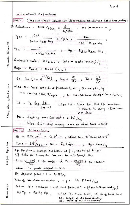
EE2355 Design of Electrical Machines Important Formulas and Expressions


EE2355 Design of Electrical Machines Important Formulas and Expressions

Anna University


Department of Electrical and Electronics Engineering

dem


Sixth Semester


EE2355 Design of Electrical Machines


(Regulation 2008)

Important Formulas and Expressions

clip_image002

clip_image002[4]

clip_image002[6]

EE2354 Microprocessors and Microcontroller Question Bank–2013 Edition


EE2354 Microprocessors and Microcontroller Question Bank–2013 Edition

Anna University
Department of Electrical and Electronics Engineering
EE2354 Microprocessors and Microcontroller Question Bank
QUESTION BANK
SUBJECT NAME : MICROPROCESSORS AND MICROCONTROLLER
YEAR / SEM : III / VI


UNIT-I
8085 PROCESSOR
PART-A (2 marks)
1. What is the need for ALE signal in 8085 microprocessor?
2. How many machine cycles are needed to execute STA 1800?
3. What is the need for interfacing?
4. Compare memory mapped I/O and peripheral mapped I/O.
5. What is memory mapping?
6. What is interfacing?
7. What are Hardware interrupts?.
8. What are Software interrupts,
9. What is interrupt?
10. What is vectored and non vectored interrupts?
11. What is the need for timing diagram?
12. Define i) Instruction cycle
ii) Machine cycle
13. Define T-state and In which T-cycle the ALE signal is activated?
14. What is masking and why it is needed?
15. What are the different addressing modes of 8085?
PART-B (16 marks)
1. Describe the functional pin diagram of 8085. (16 Marks)
2. Describe the functional block diagram of 8085. (16 Marks)
3. Explain the 8085 interrupt system in detail. (16 Marks)
4. Explain various machine cycles supported by 8085. (16 Marks)
5. a) With suitable examples explain how I/O devices are connected using memory
mapped I/O and peripheral I/O. (10 Marks)
b) Design a microprocessor system to interface an 8K × 8 EPROM and
8K × 8 RAM. (6 Marks)
6. Draw timing diagrams for the following instruction with appropriate control and
status signal. Explain in brief. CALL 2000 (16 Marks)
7. Explain the addressing modes of 8085 with example. (16 Marks)
8. Explain the Different types of instruction in 8085. (16 Marks)
9. Write the program to count from 0 to 9 with a one second delay between each
count. At the count of 9, the counter should reset itself to 0 and repeat the
sequence continuously. Use register pair HL to set up the delay, and display
each count at one of the output ports. Assume clock frequency of the 8085
microprocessor as 1MHz. (16 Marks)


UNIT-II
PERIPHERALS INTERFACING OF 8085
PART-A (2 marks)
1. List the operation modes of 8255
2. Define PPI.
Define USART.
3. What is key debouncing?
5. How a keyboard matrix is formed in keyboard interface using 8279?
6. Name any two type of ADC’S. .
7. What is the output modes used in 8279?
8. What are the modes used in keyboard modes?
9. What are the modes used in display modes?
10. How the RS -232C serial bus is interfaced to 1TL logic device?
PART-B (16 marks)
1. Explain any one of the modes of 8255 in detail. (16 Marks)
2. With neat block diagram explain PPI. (16 Marks)
3. i) Using model, write a program to communicate between two microprocessors
using 8255. (10 Marks)
ii) Show the control word format of 8255 and explain how each bit is
programmed. (6 Marks)
4. With neat block diagram explain the functions of 8251. (16 Marks)
5. i) Bring about the features of 8251. (6 Marks)
ii) Discuss how 8251 is used for serial communication of data. (6 Marks)
iii) Explain the advantages of using the USART chips in microprocessor based
systems. (4 Marks)
6. Design an interface circuit needed to connect DIP switch as an input device and
display the value of the key pressed using a 7 segment LED display. Using 8085
system, write a program to implement the same. (16 Marks)
7. i) Explain the advantages of using the keyboard and display controller chips in
microprocessor based system. (6 Marks)
ii) Write a program using RST 5.5 interrupt to get an input from keyboard and
display it on the display system. (6 Marks)
iii) Use RST 5.5 instead of RST 7.5 and change mask pattern accordingly.
(4 Marks)
8. With neat diagram explain the ADC interface to microprocessor. (16 Marks)
9. Explain in detail the RS 232C interface. (16 Marks)
10. i) How data is transformed by I2C Bus? Explain with timing diagram?
ii) What are different modes of I2C Bus? Explain in detail. (16 Marks)
11. Write a short note on GPIB. (16 Marks)


UNIT-III
8086 MICROPROCESSOR
PART-A (2 marks)
1. Define pipelining?
2. Discuss the function of instruction queue in 8086?
3. What is the maximum memory size that can be addressed by 8086?
4. What is the function of the signal in 8086?
5.What are the predefined interrupts in 8086?.
6. What are the different flag available in status register of 8086?
7. List the various addressing modes present in 8086?
8. How single stepping can be done in 8086?
9. State the significance of LOCK signal in 8086?
10. What are the functions of bus interface unit (BIU) in 8086?
11. What is the clock frequency of 8086?
12. What are the two modes of operations present in 8086?
13. Explain the process control instructions
14. What is the purpose of segment registers in 8086?
15. What are the three classifications of 8086 interrupts?
16. What are the functions of status pins in 8086?
17. Give the instruction set of 8087?.
18. How do 8086 interrupts occur?
19. What are the 8086 interrupt types?
20. What is interrupt service routine?
21. What is interfacing?
22. What is meant by interrupt?
PART-B (16 marks)
1. Discuss the various addressing modes of 8086 microprocessor. (16 Marks)
2. Explain the internal block diagram of 8086. (16 Marks)
3. Draw the pin diagram of 8086 CPU with its control signals. (16 Marks)
4. Explain various data addressing modes of 8086 with the help of examples.
(16 Marks)
5. Explain the interrupt mechanism, types and priority of 8086 microprocessor.
(16 Marks)
6. Explain the instruction set of 8086 microprocessor. (16 Marks)
7. i) Describe what happens to the status flags as the sequence of instructions that
follows is executed in 8086 microprocessor architecture. (8 Marks)
Assume that flags ZF, SF, CF, AF, OF and PF are initially reset.
MOV AX, 1234H
MOV BX, 0ABCDH
CMP AX,BX
ii) List out the shift instructions and rotate instructions in 8086. Give example for
each. (8 Marks)
8. ii) Draw the structure of 8086 flag register and explain the function of the flags
with examples. (8 Marks)
ii) Explain the functions of following 8086 signals.
1. HLDA 2. RQ/GTO 3. DEN 4. ALE (8 Marks)


UNIT-IV
8051 MICROCONTROLLER
PART-A (2 marks)
1. What is Microcontroller?
2. List the features of 8051 microcontroller.
3. Name the five interrupt sources of 8051?.
4. Explain the contents of the accumulator after the execution of the following
program segments:
5. Write a program to load accumulator A, DPH and DPL with 30H.
6. Write a program to subtract the contents of R1 of Bank0 from the contents of R0
of Bank2.
7. What is the difference between the Microprocessors and Microcontrollers?
8. Explain the functions of the pin PSEN of 8051.
9.Name the special functions register SP of 8051.
10.How the program memory is organized in 8051 based system?
PART-B (16 marks)
1. Describe the architecture of 8051 with neat diagram. (16 Marks)
2. i) Discuss the peripheral interface of 8051. (8 Marks)
ii) Explain the memory structure of 8051. (8 Marks)
3. Explain the interrupt structure of 8051 microcontroller Explain how interrupts are
prioritized. (16 Marks)
4. Explain the I/O port structure of 8051. (16 Marks)
5. Explain the different serial communication modes in 8051. (16 Marks)
6. Explain the function and operating modes of timer in 8051. (16 Marks)
7. Explain the functional pin diagram of 8051 Microcontroller. (16 Marks)


UNIT-V
8051 PROGRAMMING AND APPLICATIONS
PART-A (2 marks)
1. Explain the operating mode0 of 8051 serial ports?
2. Explain the operating mode2 of 8051 serial ports?
3. Explain the mode3 of 8051 serial ports?
4.Write A program to perfom multiplication of 2 nos using 8051?
5. List the addressing modes of 8051?
6. Write about CALL statement in 8051?
7. Write about the jump statement?
8. Write program to load accumulator ,DPH,&DPL using 8051?
9. What is subroutine or procedure?
10. What is the function of SWAP?
11. What is Assembly Language Program?
12. What is debugging?
.
PART-B (16 marks)
1. i) Write 8051 ALP to read data from port I when negative edge triggered at INT0
and supply the data to port 2 by masking the upper 4 bits. (8 Marks)
ii) Write 8051 ALP to transmit ‘Hello World’ to PC at 9600 baud for external
crystal frequency of 11.0592MHz. (8 Marks)
2. With a neat circuit diagram explain how a 4 _ 4 keypad is interfaced with 8051
microcontroller and write 8051 ALP for keypad scanning. (16 Marks)
3. Draw the schematic for interfacing a stepper motor with 8051 microcontroller and
write 8051 ALP for changing speed and direction of motor. (16 Marks)
4. Draw the schematic for interfacing a servo motor with 8051 microcontroller and
write 8051 ALP for servo motor control. (16 Marks)
5. Explain the instruction set of 8051 microcontroller. (16 Marks)
6. i) Add the unsigned number found in 8051 microcontroller internal RAM locations
25h, 26h and 27h together and put the result in RAM locations 30h (MSB) and
31h (LSB). (6 Marks)
ii) List out the arithmetic operations of 8051 microcontroller with an example and
show how the flags are affected for each operation. (10 Marks)
7. i) Write the Analog to Digital conversion program in 8051 microcontroller to
convert analog data into digital. Digitalize the input for every 100μs and store the
1000 values in external RAM location 4000b to 43E7h. (8 Marks)
ii) Explain the JUMP instructions present in 8051 microcontroller with a
mnemonic code and its operation for each. (8 Marks)

CE2253 Applied Hydraulic Engineering Question Bank for May / June 2013 Exam


CE2253 Applied Hydraulic Engineering Question Bank for May / June 2013 Exam

Anna University
QUESTION BANK
DEPARTMENT: CIVIL
SEMESTER: IV
CE2253 Applied Hydraulic Engineering
SUBJECT CODE / Name: CE 2253/APPLIED HYDRAULIC ENGINEERING


UNIT – I: OPEN CHANNEL FLOW
PART - A (2 Marks)

1. Distinguish between open channel flow and conduit flow.
2. What are wide channels?
(AUC Nov/Dec 2010) (AUC Nov/Dec 2010)
3. Define open channel flow ? (AUC Apr/May 2010)
4. Compute the hydraulic mean depth of a small channel 1m wide, 0.5m deep with water flowing at m/s. (AUC Apr/May 2010)
5. Define Specific energy of flowing liquid. (AUC Apr/May 2011)
6. How do you find the critical depth of flowing water? (AUC Apr/May 2011)
7. What are the different types of flow in open channel? (AUC Apr/May 2012)
8. Define Specific energy. (AUC Apr/May 2012)
9. Write Renold’s number for different states of flow in an open channel.
10. “Critical flow section is an excellent control section” – Justify the statement.
11. In an open channel of rectangular section if the minimum specific energy is 6 m, what is its critical depth?
12. A rectangular channel carries a flow of 4m3/s/m, what is the critical depth?
13. What are the different types of varied flows?
14. What is an isovel?
15. Define hydraulic depth(D) of an open channel flow.

PART –B (16 Marks)
1. How do you classify open channels? Explain in detail. Also explain the velocity distribution in open channel. (AUC Nov/Dec 2010)
2. Write short notes on the following:
(i) Critical flow and its computations
(ii) Channel Transition (AUC Nov/Dec 2010)
3. (i) Define specific energy. How would you express the specific energy for a wide rectangular channel with depth of flow ‘D’ and velocity of flow ‘V’? Draw the typical specific energy diagram and explain its features.
(ii) Calculate the specific energy, critical depth and velocity for the flow of 10m3/s in a cement lined rectangular channel 0.5m wide with 2m depth of water. Is the given flow subcritical or supercritical? (AUC Apr/May 2010)
4. (i) Define Froude number FR. Describe the flow for FR = , FR < and FR >1. Represent a discharge versus depth curve for a constant specific energy and explain its features.
(ii) A trapezoidal channel has a bottom width of 6.1m and side slopes of 2H: 1V. When the depth of flow is 1.07 m, the flow is 10.47 m3/s? What is the specific energy of flow? Is the flow tranquil or rapid? (AUC Apr/May 2010)
5. A trapezoidal channel with side slopes of 2 horizontal: 3 vertical has to carry 20 m3/sec.
Find the slope of the channel when the bottom width of the channel is m and the depth of the water is 3 m. Take Manning’s n = 0.03. (AUC Apr/May 2011)
6. Calculate the specific energy of 12m3/sec of water flowing with a velocity of 1.5 m/s in a rectangular channel 7.5m wide. Find the depth of water in the channel when the specific energy would be minimum. What would be the value of critical velocity as well as minimum specific energy? (AUC Apr/May 2011)
7. (i) How are the flows classified under specific energy concepts?
(ii) A 8m wide channel conveys 15 cumecs of water at a depth of 1.2m. Determine
(1) Specific Energy of the flowing water (2) Critical depth, critical velocity and minimum specific energy (3) Froude number and state whether the flow is subcritical or supercritical. (AUC Apr/May 2012)
8. (i) Explain the salient features of Specific Energy curve.
(ii) Determine the critical depth for a specific energy of 1.5 m in the following channels
(1) Rectangular channel
(2) Triangular channel
(3) Trapezoidal channel. (AUC Apr/May 2012)
9. (i) Find the critical depth for a specific energy of 1.5 m in: (1) Rectangular channel of bottom width 2m (2)Triangular channel of side slope 1:1.5
(3)Trapezoidal channel of bottom width 2m and side slope 1:1? (ii) What are the different types and states of flow in open channel?
10. (i) Prove that for critical flow specific is minimum.
(ii) Calculate the width of a rectangular channel required to carry a discharge 15m3/s as critical flow at a depth of 1.2m.


UNIT – II: UNIFORM FLOW
PART - A (2 Marks)

1. Mention the significance of Manning’s formula. (AUC Nov/Dec 2010)
2. What are the essential conditions for most economical section? (AUC Nov/Dec 2010)
3. Write down the Chezy’s formula for determining velocity of flow in an open channel. (AUC Apr/May 2010)
4. Show that the maximization of discharge requires maximization of the wetted perimeter of the channel for a given area of flow. (AUC Apr/May 2010)
5. Distinguish between uniform and non-uniform. (AUC Apr/May 2011)
6. Define the Froude Number. What is its significance? (AUC Apr/May 2011)
7. Distinguish between normal depth and critical depth. (AUC Apr/May 2012)
8. What are the conditions for the most economical triangular channel section?
(AUC Apr/May 2012)
9. Define ‘conveyance’ of an open channel.
10. Why are best hydraulic sections in open channel flow referred as most economical sections?
11. A river with a lined banks has a Manning’s n = 0.014, and Chezy’ C = 55, What is its hydraulic radius?
12. What is equivalent roughness or composite roughness of an open channel?
13. What are the geometric conditions for a triangular channel to be most economic?
14. Define normal discharge and normal slope.
15. Define uniform flow.
PART –B (16 Marks)
1. A channel is designed to carry a discharge of 20 m3/s with Manning’s n = 0.015 and bed slope of 1 in 1000 (for trapezoidal channel side slope M = 1√3). Find the channel dimensions of the most efficient section if the channel is (i) trapezoidal
(ii) rectangular. (AUC Nov/Dec 2010)
2. Explain the computation of uniform flow using Manning’s and Chezy’s method. (AUC Nov/Dec 2010)
3. (i) A V – shaped open channel of included angle 90º conveys a discharge of 0.05 m3/s when the depth of flow at the center is 0.225 m. Assuming that C = 50 m1/2/s in the Chezy’s equation, calculate the slope of the channel.
(ii) Calculate the dimensions of the rectangular cross-section of an open channel which requires minimum area to convey 10 m3/s. The slope being in 1500. Take the Manning’s ‘N’ as 0.013. (AUC Apr/May 2010)
4. Derive the expressions for the most economical depths of flow of water in terms of the diameter of the channel of circular cross-section:
(i) For maximum velocity and
(ii) For maximum discharge. (AUC Apr/May 2010)
5. (i) Derive the Chezy’s equation for steady uniform flow.
(ii) Derive the relationship for most economical trapezoidal channel. (AUC Apr/May 2011)
6. A power canal of trapezoidal section has to be excavated through hard clay at the least cost. Determine the dimensions of the channel given, discharge equal to 14 m3/s, bed slope 1/2500, Manning’s n = 0.02. (AUC Apr/May 2011)
7. (i) Show that the hydraulic radius is half the flow depth for the most economical trapezoidal channel section.
(ii) Determine the most economical section of rectangular channel carrying water at the rate of 0.6 cumecs. The bed slope is 1 in 2000. Assume Chezy’s constant C = 50. (AUC Apr/May 2012)
8. (i) How do you determine velocity of flow in open channel?
(ii)The bed width of a trapezoidal channel section is 40 m and the side slope is 2 horizontal to 1 vertical. The discharge in the canal is 60 cumecs. The Manning’s ‘n’ is 0.015 and the bed slope is 1 in 5000. Determine the normal depth. (AUC Apr/May 2012)
9. Derive the geometrical properties of a most economical triangular channel section.
10. (i) A rectangular channel of width 15m has abed slope of 0.00075 and Manning’s n = 0.016. Compute the normal depth to carry a discharge of 50m3/s?
(ii)Explain the graphical method of determination of normal depth for a trapezoidal channel.


UNIT – III: VARIED FLOW

PART - A (2 Marks)
1. What are the assumptions made in dynamic equation for gradually varied flow?
(AUC Nov/Dec 2010)
2. What is mean by back water curve? (AUC Nov/Dec 2010)
3. What is a draw down curve? (AUC Apr/May 2010)
4. Indicate the usefulness of hydraulic jump. (AUC Apr/May 2010)
5. What is the energy loss in a hydraulic jump? (AUC Apr/May 2011)
6. How is back water curve formed? (AUC Apr/May 2011)
7. Write down the dynamic equation of gradually varied flow. (AUC Apr/May 2012)
8. Distinguish between positive and negative surges. (AUC Apr/May 2012)
9. Differentiate between draw down and back water curves.
10. Define sequent depth.
11. What is the nature of slope of the channel if critical depth line occurs above normal depth line?
12. What is the state of flow after formation of a hydraulic jump?
13. What is the control section of an open channel flow?
14. What are the assumptions in varied flow?
15. Write two methods used for flow profile determination.

PART – B (16 Marks)

1. How do you classify surface profiles? Briefly explain the various salient features of various profiles. Also write a note on hydraulic jump. (AUC Nov/Dec 2010)

2. A 50 m long laboratory flume has a rectangular section with a width of 2m and ends in a free overall. The channel is made of glass and the bed drops by 5 cm in the entire length. At a certain discharge, it was seen that the depth near the channel entrance was more or less constant at 0.5 m. Use the direct step method to obtain the length of profile. Use two equal depth increments. (AUC Nov/Dec 2010)

3. (i) In a given channel, Yo and Yc are two fixed depths if Q, N and So are fixed. Also, there are three possible relation between Yo and Yc. Further, there are two cases where You does not exist. Based on these, how the channels are classified?
(ii)A river 100 m wide and 3m deep has an average bed slope of 0.0005. Estimate the length of the GVF profile produced by a low weir which raises the water surface just upstream of it by 1.5 m. Assume N = 0.035. Use direct step method with three steps. (AUC Apr/May 2010)

4. (i) Explain the classification of hydraulic jumps.
(ii) A spillway discharges a flood flow at a rate of 7.75 m3/s per metre width. At the downstream horizontal apron the depth of flow was found to be 0.5 m. What tail water depth is needed to form a hydraulic jump? If a jump is formed, find its type, length, head loss and energy loss as a percentage of the initial energy. (AUC Apr/May 2010)

5. In a rectangular channel of 0.5 m width, a hydraulic jump occurs at a point where depth of water flow is 0.15 m and Froude number is 0.5. Determine
(i) The specific energy
(ii) The critical and subsequent depths
(iii) Loss of head and
(iv) Energy dissipated. (AUC Apr/May 2011)

6. A river of 45 m wide has a normal depth of flow of 3 m and an average bed slope of in 10,000.A weir is build across the river raising the water surface level at the weir site to 5 m above the bottom of the river. Assuming that the back water curve is an arc of circle; calculate the approximate length of the curve. Manning’s n = 0.025.(AUC Apr/May 2011)

7. (i) What are the assumptions made in the analysis of gradually varied flow?
(ii)The bed width of a rectangular channel is 24 m and the depth of flow is 6m. The discharge in the canal is 86 cumecs. The bed slope of the channel is 1 in 4000. Assume Chezy’s constant C = 60. Determine the slope of the free water surface. (AUC Apr/May 2012)

8. (i)What are the conditions for the formation of hydraulic jump?
(ii)In a rectangular channel of bed width 0.5 m, a hydraulic jump occurs at a point where depth of flow is 0.15 m and Froude’s number is 2.5. Determine
(1) The specific energy (2) The critical depth (3) The subsequent depths (4) Loss of head (5) Energy dissipated. (AUC Apr/May 2012)

9. (i) A rectangular channel carries a flow with a velocity of 0.65m/s and depth of 1.4m. If the discharge is abruptly increased three fold by sudden lifting of a gate on the upstream side, estimate the velocity and height of the resulting surge?
(ii)With neat diagrams explain different types of channel transitions.

10. (i)Write the gradually varied flow equation in an open channel flow. Deduce the equation for a wide rectangular channel using Manning’s and chezy’s equation.
(ii)Explain with a neat diagram the surges produced when (i) a sluice gate is suddenly raised (ii)sluice gate is suddenly lowered.


UNIT – IV: PUMPS
PART - A (2 Marks)

1. Define Priming. (AUC Nov/Dec 2010)
2. What is the significance of air vessel? (AUC Nov/Dec 2010)
3. Why is the theoretical suction height of a pump limited? (AUC Apr/May 2010)
4. Define negative slip. How it occurs? (AUC Apr/May 2010)
5. What are the differences between jet pump and submersible pump?
(AUC Apr/May 2011)
6. Draw an ideal indicator diagram. (AUC Apr/May 2011)
7. Define specific speed of a pump. (AUC Apr/May 2012)
8. Draw the indicator diagram for a single acting reciprocating pump.
2012)Why submersible pump named so?
9. Differentiate between a rotodynamic pump and rotary pump.
10. What is the function of foot valve in a pump?
(AUC Apr/May
11. What is the condition for finding the minimum starting speed of centrifugal pump?
12. Name two rotary pumps.
13. What are multistage pumps?
14. For a single acting reciprocating pump what are the angles at which there is no flow into and out of the air vessel?

PART –B (16 Marks)
1. A single acting reciprocating pump having a cylinder diameter of 150 mm and stroke of 300 mm is used to raise the water through a height of 20 m. Its crank rotates at 60 rpm. Find the theoretical power required to run the pump and the theoretical discharge. If actual discharge is 5 lit/s find the percentage of slip. If delivery pipe is 100 mm in diameter and is 15 m long, find the acceleration head at the beginning of the stroke. (AUC Nov/Dec 2010)

2. Discuss in detail the working of Centrifugal pump. Also write a note on working of jet pump. (AUC Nov/Dec 2010)

3. (i) With the help of neat sketches, explain the features of a volute type and a diffusion type centrifugal pump
(ii)A centrifugal pump delivers salt water against a head of 15 m at a speed of 100 rpm. The vanes are curved backward at 30º with the periphery. Obtain the discharge for an impeller diameter of 30 cm and outlet width of 5 cm at a manometric efficiency of 90%.
(AUC Apr/May 2010)

4. (i) Draw the indicator diagram of a reciprocating pump for the following cases : (1) Without air vessels on both suction and delivery sides.
(2) With air vessel only on suction side.
(ii) For a hydraulic machine installed between A and B, the following data is available: At A At B
Diameter 20cm 30cm Elevation 105m 100m Pressure 100 kPa 200 kPa
The direction of flow is from A to B and the discharge is 200 litres per second. Is the machine a pump or a turbine? (AUC Apr/May 2010)

5. The impeller of a centrifugal pump having external and internal diameters 500 mm and
250 mm respectively, width at outlet 50 mm and running at 1200rpm. Works against a head of 48 m. The velocity of flow through the impeller is constant and equal to 3 m/s. The vanes are set back at an angle of 40º at outlet. Determine
(i) Inlet Vane angle
(ii) Work –done by the impeller and Manometric efficiency. (AUC Apr/May 2011)

6. A three throw pump has cylinders of 250 mm diameter and stroke of 500 mm each. The pump is required to deliver 0.1 m3/sec at a head of 100 m. Friction losses are estimated to be m in the suction pipe and 19 m in delivery pipe. Velocity of water in delivery pipe is m/s, overall efficiency is 85% and the slip is 3% Determine
(i) Speed of the pump and
(ii) Power required for running the pump. (AUC Apr/May 2011)

7. (i) Define
(1) Manometric efficiency (2) Volumetric efficiency (3) Mechanical efficiency
(4) Overall Efficiency of Centrifugal pump.
(ii) The impeller of a centrifugal pump has an external diameter of 450 mm and internal diameter of 200 mm. The speed of the pump is 1440 rpm. Assuming a constant radial flow through the impeller at 2.5 m/s and that the vanes at exit are set back at an angle of
25º, Determine:
(1) The inlet vane angle
(2) The angle, the absolute velocity of water at exit makes with the tangent and
(3) The work done per unit weight. (AUC Apr/May 2012)

8. (i) Explain the working principle of double acting reciprocating pump with a neat sketch. (ii) Length of 350 mm. The speed of the pump is 60 rpm and the discharge is
0.02cumecs of water. Determine (1) The theoretical discharge (2) Coefficient of discharge
(3) Percentage slip. (AUC Apr/May 2012)

9. (i) Compare and contrast Centrifugal pump and reciprocating pump.
(ii)The cross sectional area of a plunger of reciprocating pump equals 1.5 times that of a delivery pipe. The delivery pipe is 60m long and it rises upward at a slope of 1 in 6. If the plunger has an acceleration of 2.4m/s2 at the end of the stroke and separation pressure is 2.5m of water find whether separation will take place.

10. (i)Explain the different types of Reciprocating pumps? (ii)Differentiate pumps and turbines.


UNIT – V: TURBINES

PART - A (2 Marks)
1. Distinguish between impulse and reaction turbines. (AUC Nov/Dec 2010)
2. What is cavitation? How do you prevent cavitation? (AUC Nov/Dec 2010)
3. Classify Pelton turbine according to
(a) The direction of flow through the turbine runner
(b) The action of water on turbine blades. (AUC Apr/May 2010)
4. Define specific speed of a turbine. (AUC Apr/May 2010)
5. What is the use of draft tube? (AUC Apr/May 2011)
6. Define the specific speed of a turbine. (AUC Apr/May 2011)
7. How would you classify turbines based on the direction of flow in the runner?
(AUC Apr/May 2012)
8. Draw typical velocity triangles for inlet and outlet of Pelton wheel.
(AUC Apr/May 2012)

PART –B (16 Marks)
1. A Pelton wheel operates with a jet of jet of 150 mm diameter under the head of 500 m, its mean runner diameter is 0.25 m and it rates with a speed of 375 rpm. The angle of bucket tip at outlet as 15º, coefficient of velocity is 0.98, mechanical losses equal to 3% of power supplied and the reduction in relative velocity of water while passing through bucket is 15%. Find (i) the force of jet on the bucket (ii) the power developed (iii) bucket efficiency and (iv) overall efficiency. (AUC Nov/Dec 2010)

2. Derive the equation for power and work done for the impact of jets on moving curved vanes. Explain the classification of turbines. (AUC Nov/Dec 2010)

3. (i) Classify the turbines based on :
(1) Action of water on turbine blades. (2) Head on turbine.
(3) Direction of flow through turbine runner. (4) Specific speed.
(5) Disposition of turbines shaft.
(ii) A Pelton turbine is required to develop 9000 kW when working under a head of 300 m. The runner may rotate at 500 rpm. Assuming the jet ratio as 10, speed ratio as 0.46 and overall efficiency as 85%, determine the following:
(1) Quantity of water required
(2) Diameter of the wheel
(3) Number of jets
(4) Number of buckets. (AUC Apr/May 2010)

4. (i) Draw the characteristics curves of turbines and explain.
(ii) An inward flow reaction turbine operates under a head of 25 m running at 200 rpm. The peripheral velocity at the runner is 20 m/s and the radial velocity at the runner exit is
5 m/s. If the hydraulic losses are 20% of the available head, calculate: (1) The guide-vane exit angle
(2) The runner-vane angle
(3) The runner diameter
(4) The specific speed, if the width of the runner at the periphery is 30 cm and
(5) The power produced by the turbine. (AUC Apr/May 2010)

5. A Pelton wheel generates 8000 kW under a net head of 130 m at a speed of 200 rpm.
Assuming the coefficient of velocity for the nozzle 0.98, hydraulic efficiency 87%, speed ratio 0.46 and jet diameter to wheel diameter ratio 1/9, Determine,
(i) Discharge required
(ii) Diameter of the wheel
(iii) Diameter and number of jets required and
(iv) Specific speed of the turbine. Take Mechanical efficiency is 75%.
(AUC Apr/May 2011)

6. In an inward flow reaction turbine, head on turbine is 32 m. The external an internal diameters are 0.44 m and 0.72 m respectively. The velocity of flow through the runner is constant and equal to 3 m/s. The guide blade angle is 10º and runner vanes are rigid at inlet. If the discharge at outlet is radial, determine
(i) The speed of the turbine
(ii) The vane angle at outlet of the runner and
(iii) Hydraulic efficiency. (AUC Apr/May 2011)

7. (i) Distinguish between impulse and reaction turbines.
(iii) A Pelton wheel is required to develop 8825 kW when working under the head of 300 m. The speed of the pelton wheel is 540 rpm. The coefficient of velocity is 0.98 and the speed ratio is 0.46. Assuming jet ratio as 10 and overall efficiency as 84%. Determine :
(1) The number of jets
(2) The diameter of the wheel
(3) The quantity of water required (AUC Apr/May 2012)

8. (i) What are the various types of draft tube?
(ii) A Francis turbine is to be designed to develop 360 kW under a head of 70 m and a speed of 750 rpm. The ratio of width of runner to diameter of runner ‘n’ is 0.1. The inner diameter of the runner is half the outer diameter. The flow ratio is 0.15. The hydraulic efficiency is 95% and the mechanical efficiency is 84%. Four percent of the circumferential area of runner is to be occupied by the thickness of the vanes. The velocity of flow is constant and the discharge is radial at exit.
Determine:
(1) The diameter of the wheel
(2) The quantity of water supplied
(3) The guide vane angle at inlet and
(4) Runner vane angles at inlet and exit. (AUC Apr/May 2012)


CE2351 Structural Analysis–II Two Marks with Answers for May June 2013 Exam


CE2351 Structural Analysis–II Two Marks with Answers for May June 2013 Exam

Anna University
DEPARTMENT OF CIVIL ENGINEERING
CE 1352 – STRUCTURAL ANALYSIS - II
Questions & Answers
(Two Marks)


UNIT - I
FLEXIBILITY METHOD FOR INDETERMINATE FRAMES


1. What is meant by indeterminate structures?
Structures that do not satisfy the conditions of equilibrium are called indeterminate structure. These structures cannot be solved by ordinary analysis techniques.
2. What are the conditions of equilibrium?
The three conditions of equilibrium are the sum of horizontal forces, vertical forces and moments at any joint should be equal to zero.
3. Differentiate between determinate and indeterminate structures.Determinate structures can be solving using conditions of equilibrium alone ( H = 0; V = 0; M = 0). No other conditions are required.
Indeterminate structures cannot be solved using conditions of equilibrium because ( H ≠ 0; V ≠0; M ≠ 0). Additional conditions are required for solving such structures.

4. Define degree of indeterminacy.
The excess number of reactions that make a structure indeterminate is called degree of
Indeterminacy. Indeterminacy is also called degree of redundancy.
Indeterminacy consists of internal and external indeterminacies.
It is denoted by the symbol ‘i’
Degree of redundancy (i) = I.I. + E.I.
Where I.I. = internal indeterminacy and E.I. = external indeterminacy.

5. Define internal and external indeterminacies.
Internal indeterminacy (I.I.) is the excess no of internal forces present in a member that make a structure indeterminate.
External indeterminacy (E.I.) is excess no of external reactions in the member that make the structure indeterminate.
Indeterminacy = I.I. + E.I.
E.I. = r – e; where r = no of support reactions and e = equilibrium conditions
I.I. = i – EI
e = 3 (plane frames) and e = 6 (space frames)

6. Write the formulae for degree of indeterminacy for:
(a) Two dimensional pinjointed truss (2D Truss)
i = (m+r) – 2j where m = no of members
r = no of reactions; j = no of joints
(b) Two dimensional rigid frames/plane rigid frames (2D Frames)
i = (3m+r) – 3j where m = no of members
r = no of reactions; j = no of joints
(c) Three dimensional space truss (3D Truss)
i = (m+r) – 3j where m = no of members
r = no of reactions; j = no of joints
(d) Three dimensional space frames (3D Frame)
i = (6m+r) – 6j where m = no of members
r = no of reactions; j = no of joints

7. Determine the degree of indeterminacy for the following 2D truss.
i = (m+r) - 2j
Where, m = 19; r = 4; j = 10; e = 3 i = (19+4) – 2 x 10 = 3
External indeterminacy E.I. = r – e = 4 – 3 = 1
Internal indeterminacy I.I. = i – E.I. = 3 -1 = 2

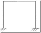
8. Determine the total, internal and external degree of indeterminacy for the plane rigid frame below.
i = (3m + r) – 3j
Where, m = 7; r = 4; j = 6; e = 3 i = (3 x 7 + 4) – (3 x 6) = 7
External indeterminacy E.I. = r – e = 4 – 3 = 1
Internal indeterminacy I.I. = i – EI = 7 -1 = 6

9. Determine i, EI, II for the given plane truss.
i = (m + r) – 2j
Where, m = 3; r = 4; j = 3; e = 3 i = (3 + 4) – (2 x 3) = 1
External indeterminacy EI = r – e = 4 – 3 = 1
Internal indeterminacy II = i – EI = 1 -1 = 0

10. Find the indeterminacy for the beams given below.
For beams degree of indeterminacy is given by i = r – e
(a) clip_image006
i = r – e where, r = no of reactions, e = no of equilibrium conditions r = 4 and e = 3
i = 4 – 3 = 1
(b) clip_image008
i = r – e where, r = no of reactions, e = no of equilibrium conditions r = 5 and e = 3
i = 5 – 3 = 2
clip_image010
11. Find the indeterminacy for the given rigid plane frame.
i = (3m + r) – 3j
Where, m = 3; r = 4; j = 4
i = (3 x 3 + 4) – (3 x 4) = 1
External indeterminacy EI = r – e = 4 – 3 = 1
Internal indeterminacy II = i – EI = 1 - 1 = 0

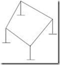
12. Find the indeterminacy of the space rigid frame.
i = (6m + r) – 6j
Where, m = 8; r = 24 (i. e. 6 per support x 4)
j = 8; e = 6
i = (6 x 8 + 24) – (6 x 8) = 24
clip_image012
External indeterminacy EI = r – e = 24 – 6 = 18
Internal indeterminacy II = i – EI = 24 -18 = 6
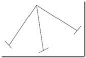
13. Find the indeterminacy for the given space truss.
i = m + r – 3j
clip_image014
Where m = 3
r = 18 (i. e. 6 reactions per support x 3)
j = 4
i = (3 + 18) – (3 x 4) = 9
External indeterminacy EI = r – e = 18 – 6 = 12
Internal indeterminacy II = i – EI = 9 -12 = –3

14. What are the different methods of analysis of indeterminate structures?
The various methods adopted for the analysis of indeterminate structures include:
v Flexibility matrix method
v Stiffness matrix method
v Finite Element method

15. Briefly mention the two types of matrix methods of analysis of indeterminate structures.
The two matrix methods of analysis of indeterminate structures are: (i) Flexibility matrix method:
This method is also called the force method in which the forces in the structure are treated as unknowns. The no of equations involved is equal to the degree of static indeterminacy of the structure.
(ii) Stiffness matrix method:
This is also called the displacement method in which the displacements that occur in the structure are treated as unknowns. The no of displacements involved is equal to the no of degrees of freedom of the structure.

16. Define a primary structure.
A structure formed by the removing the excess or redundant restraints from an indeterminate structure making it statically determinate is called primary structure. This is required for solving indeterminate structures by flexibility matrix method.

17. Define kinematic indeterminacy (Dk) or Degree of Freedom (DOF)
Degree of freedom is defined as the least no of independent displacements required to define the deformed shape of a structure.
There are two types of DOF: (a) Nodal type DOF and (b) Joint type DOF.

18. Briefly explain the two types of DOF.
(a) Nodal type DOF – This includes the DOF at the point of application of concentrated load or moment, at a section where moment of inertia changes, hinge support, roller support and junction of two or more members.
(b) Joint type DOF – This includes the DOF at the point where moment of inertia changes, hinge and roller support, and junction of two or more members.

19. For the truss shown below, what is the DOF?
Pin-jointed plane frame/truss
DOF / Dk = 2j – r
Where, r = no of reactions; j = no of joints

clip_image016


20. Define compatibility in force method of analysis .
Compatibility is defined as the continuity condition on the displacements of the structure after external loads are applied to the structure.

21. Define the Force Transformation Matrix.
The connectivity matrix which relates the internal forces Q and the external forces R is known as the force transformation matrix. Writing it in a matrix form,
{Q} = [b] {R}
Where, Q = member force matrix/vector; b = force transformation matrix
R = external force/load matrix/ vector

22. What are the requirements to be satisfied while analyzing a structure?
The three conditions to be satisfied are: (i) Equilibrium condition
(ii) Compatibility condition
(iii) Force displacement condition

23. Define flexibility influence coefficient (fij)
Flexibility influence coefficient (fij) is defined as the displacement at joint ‘i’ due to a unit load at
joint ‘j’, while a l other joints are not load.

24. Write the element flexibility matrix (f) for a truss member & for a beam element.
The element flexibility matrix (f) for a truss member is given by
clip_image018
The element flexibility matrix (f) for a beam element is given by
clip_image020


U
NIT - II
MATRIX STIFFNESS METHOD


1. What are the basic unknowns in stiffness matrix method?
In the stiffness matrix method nodal displacements are treated as the basic unknowns for the solution of indeterminate structures.

2. Define stiffness coefficient kij.
Stiffness coefficient ‘kij’ is defined as the force developed at joint ‘i’ due to unit displacement at
joint ‘j’ while a l other joints are fixed.

3. What is the basic aim of the stiffness method?
The aim of the stiffness method is to evaluate the values of generalized coordinates ‘r’ knowing
the structure stiffness matrix ‘k’ and nodal loads ‘R’ through the structure equilibrium equation.
{R} = [K] {r}

4. What is the displacement transformation matrix?
The connectivity matrix which relates the internal displacement ‘q’ and the external displacement
‘r’ is known as the displacement transformation matrix ‘a’.
{q} = [a] {r}

5. How are the basic equations of stiffness matrix obtained?
The basic equations of stiffness matrix are obtained as: Equilibrium forces
Compatibility of displacements
Force displacement relationships

6. What is the equilibrium condition used in the stiffness method?
The external loads and the internal member forces must be in equilibrium at the nodal points.

7. What is meant by generalized coordinates?
For specifying a configuration of a system, a certain minimum no of independent coordinates are necessary. The least no of independent coordinates that are needed to specify the configuration is known as generalized coordinates.

8. What is the compatibility condition used in the flexibility method?
The deformed elements fit together at nodal points.

9. Write about the force displacement relationship.
The relationship of each element must satisfy the stress-strain relationship of the element material.

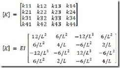
10. Write the element stiffness for a truss element.
The element stiffness matrix for a truss element is given by
clip_image024

11. Write the element stiffness matrix for a beam ele ment.
The element stiffness matrix for a beam element is given by
clip_image026

12. Compare flexibility method and stiffness method.
Flex ibility matrix method:
The redundant forces are treated as basic unknowns.
The number of equations involved is equal to the degree of static indeterminacy of the structure.
The method is the generalization of consistent deformation method. Different procedures are used for determinate and indeterminate structures
Stiffness matrix method:
The joint displacements are treated as basic unknowns
The number of displacements involved is equal to the no of degrees of freedom of the
structure
The method is the generalization of the slope deflection method.
The same procedure is used for both determinate and indeterminate structures.

13. Is it possible to develop the flexibility matrix for an unstable structure?
In order to develop the flexibility matrix for a structure, it has to be stable and determinate.

14. What is the relation between flexibility and stiffness matrix?
The element stiffness matrix ‘k’ is the inverse of the element flexibility matrix ‘f’ and is given by f = 1/k or k = 1/f.

15. What are the types of structures that can be solved using stiffness matrix method?
Structures such as simply supported, fixed beams and portal frames can be solved using stiffness matrix method.

16. Give the formula for the size of the Global stiffness matrix.
The size of the global stiffness matrix (GSM) = No: of nodes x Degrees of freedom per node.

17. List the properties of the stiffness matrix
The properties of the stiffness matrix are: It is a symmetric matrix
The sum of elements in any column must be equal to zero.
It is an unstable element therefore the determinant is equal to zero.

18. Why is the stiffness matrix method also called equilibrium method or displacement method?
Stiffness method is based on the superposition of displacements and hence is also known as the displacement method. And since it leads to the equilibrium equations the method is also known as equilibrium method.

19. If the flexibility matrix is given as
clip_image030
Write the corresponding stiffness matrix.
Stiffness matrix = 1 / (Flexibility matrix)
i.e. [K] = [F]-1

20. Write then stiffness matrix for a 2 D beam element.
The stiffness matrix for a 2 D beam element is given by
clip_image032


UNIT III
FINITE ELEMENT METHOD


1. What is meant by Finite element method?
Finite element method (FEM) is a numerical technique for solving boundary value problems in which a large domain is divided into smaller pieces or elements. The solution is determined by assuming certain polynomials. The small pieces are called finite element and the polynomials are called shape functions.

2. List out the advantages of FEM.
Ø Since the properties of each element are evaluated separately different material properties can be incorporated for each element.
Ø There is no restriction in the shape of the medium.
Ø Any type of boundary condition can be adopted.

3. List out the disadvantages of FEM.
Ø The computational cost is high.
Ø The solution is approximate and several checks are required.

4. Mention the various coordinates in FEM.
Ø Local or element coordinates
Ø Natural coordinates
Ø Simple natural coordinates
Ø Area coordinates or Triangular coordinates
Ø Generalized coordinates

5. What are the basic steps in FEM?
Ø Discretization of the structure
Ø Selection of suitable displacement function
Ø Finding the element properties
Ø Assembling the element properties
Ø Applying the boundary conditions
Ø Solving the system of equations
Ø Computing additional results

6. What is meant by discretization?
Discretization is the process of subdividing the given body into a number of elements which results in a system of equivalent finite elements.

7. What are the factors governing the selection of finite elements?
Ø The geometry of the body
Ø The number of independent space coordinates

8. Define displacement function.
Displacement function is defined as simple functions which are assumed to approximate the displacements for each element. They may assume in the form of polynomials, or trigonometrical functions.

9. Briefly explain a few terminology used in FEM.
The various terms used in FEM are explained below.
Finite element: Small elements used for subdividing the given domain to be analysed are called finite elements. These elements may be 1D, 2D or 3D elements depending on the type of structure.
Nodes and nodal points: The intersection of the different sides of elements are called nodes. Nodes are of two types – external nodes and internal nodes.
External nodes – The nodal point connecting adjacent elements.
Internal nodes – The extra nodes used to increase the accuracy of solution.
Nodal lines: The interface between elements are called nodal lines.
Continuum: The domain in which matter exists at every point is called a continuum. It can be assumed as having infinite number of connected particles.
Primary unk nowns: The main unknowns involved in the formulation of the element properties are known as primary unknowns.
Secondary unk nowns: These unknowns are derived from primary unknowns are known as secondary unknowns. In displacement formulations, displacements are treated as primary unknowns and stress, strain, moments and shear force are treated as secondary unknowns.
10. What are different types of elements used in FEM?
The various elements used in FEM are classified as: One dimensional elements (1D elements) Two dimensional elements (2D elements) Three dimensional elements (3D elements)
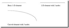
11. What are 1-D elements? Give examples.
clip_image036
Elements having a minimum of two nodes are called 1D element. Beams are usually approximated with 1D element. These may be straight or curved. There can be additional nodes within the element.

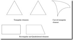
12. What are 2-D elements? Give examples.
A plane wall, plate, diaphragm, slab, shell etc. can be approximated as an assemblage of 2-D
elements. Most commonly used elements are triangular, rectangular and quadrilateral elements.
clip_image038

13. What are 3-D elements? Give examples.
3-D elements are used for modeling solid bodies and the various 3-D elements are tetrahedron, hexahedron, and curved rectangular solid.

14. Define Shape function.
Shape function is also called an approximate function or an interpolation function whose value is equal to unity at the node considered and zeros at all other nodes. Shape function is represented by Ni where i = node no.

15. What are the properties of shape functions?
The properties of shape functions are:
Ø The no of shape functions will be equal to the no of nodes present in the element.
Ø Shape function will have a unit value at the node considered and zero value at other nodes.
Ø The sum of all the shape function is equal to 1.

16. Define aspect ratio.
Element aspect ratio is defined as the ratio of the largest dimension of the element to its smallest dimension.

17. What are possible locations for nodes?
The possible locations for nodes are:
Ø Point of application of concentrated load.
Ø Location where there is a change in intensity of loads
Ø Locations where there are discontinuities in the geometry of the structure
Ø Interfaces between materials of different properties.

18. What are the characteristics of displacement functions?
Displacement functions should have the following characteristics:
Ø The displacement field should be continuous.
Ø The displacement function should be compatible between adjacent elements
Ø The displacement field must represent constant strain states of elements
Ø The displacement function must represent rigid body displacements of an element.

19. What is meant by plane strain condition?
Plane strain is a state of strain in which normal strain and shear strain directed perpendicular to the plane of body is assumed to be zero.


U
NIT – IV
PLASTIC ANALYSIS OF STRUCTURES


1. What is a plastic hinge?
When a section attains full plastic moment Mp, it acts as hinge which is called a plastic hinge. It is defined as the yielded zone due to bending at which large rotations can occur with a constant value of plastic moment Mp.

2. What is a mechanism?
When a n-degree indeterminate structure develops n plastic hinges, it becomes determinate and the formation of an additional hinge will reduce the structure to a mechanism. Once a structure becomes a mechanism, it will collapse.

3. What is difference between plastic hinge and mechanical hinge?
Plastic hinges modify the behavior of structures in the same way as mechanical hinges. The only difference is that plastic hinges permit rotation with a constant resisting moment equal to the plastic moment Mp. At mechanical hinges, the resisting moment is equal to zero.

4. Define collapse load.
The load that causes the (n + 1) the hinge to form a mechanism is called collapse load where n is the degree of statically indeterminacy. Once the structure becomes a mechanism

5. List out the assumptions made for plastic analysis.
The assumptions for plastic analysis are:
Ø Plane transverse sections remain plane and normal to the longitudinal axis before and after bending.
Ø Effect of shear is neglected.
Ø The material is homogeneous and isotropic both in the elastic and plastic state.
Ø Modulus of elasticity has the same value both in tension and compression.
Ø There is no resultant axial force in the beam.
Ø The cross-section of the beam is symmetrical about an axis through its centroid and parallel to the plane of bending.

6. Define shape factor.
Shape factor (S) is defined as the ratio of plastic moment of the section to the yield moment of the section.
clip_image040
Where Mp = Plastic moment
M = Yield moment
Zp = Plastic section modulus
Z = Elastic section modulus

7. List out the shape factors for the following sections.
(a) Rectangular section, S = 1.5
(b) Triangular section, S = 2.346 (c) Circular section, S = 1.697 (d) Diamond section, S = 2

8. Mention the section having maximum shape factor.
The section having maximum shape factor is a triangular section, S = 2.345.

9. Define load factor.
Load factor is defined as the ratio of collapse load to working load and is given by
clip_image042

10. State upper bound theory.
Upper bound theory states that of all the assumed mechanisms the exact collapse mechanism is that which requires a minimum load.

11. State lower bound theory.
Lower bound theory states that the collapse load is determined by assuming suitable moment distribution diagram. The moment distribution diagram is drawn in such a way that the conditions of equilibrium are satisfied.

12. What are the different types of mechanisms?
The different types of mechanisms are:
Ø Beam mechanism
Ø Column mechanism
Ø Panel or sway mechanism
Ø Cable mechanism
Ø Combined or composite mechanism

13. Mention the types of frames.
Frames are broadly of two types: (a) Symmetric frames
(b) Un-symmetric frames

14. What are symmetric frames and how they analyzed?
Symmetric frames are frames having the same support conditions, lengths and loading conditions on the columns and beams of the frame. Symmetric frames can be analyzed by:
(a) Beam mechanism
(b) Column mechanism

15. What are unsymmetrical frames and how are they analyzed?
Un-symmetric frames have different support conditions, lengths and loading conditions on its columns and beams. These frames can be analyzed by:
(a) Beam mechanism
(b) Column mechanism
(c) Panel or sway mechanism
(d) Combined mechanism

16. Define plastic modulus of a section Zp.
The plastic modulus of a section is the first moment of the area above and below the equal area axis. It is the resisting modulus of a fully plasticized section.
Zp = A/2 (y1 + y2)

17. How is the shape factor of a hollow circular section related to the shape factor of a ordinary circular section?
The shape factor of a hollow circular section = A factor K x shape factor of ordinary circular
section.
SF of hollow circular section = SF of circular section x {(1 – c3)/ (1 – c4)}

18. Give the governing equation for bending.
The governing equation for bending is given by
M/I = /y
Where M = Bending moment
I = Moment of inertia
y = c. g. distance

19. Give the theorems for determining the collapse load.
The two theorems for the determination of collapse load are: (a) Static Method [Lower bound Theorem]
(b) Kinematic Method [Upper bound Theorem]


U
NIT-V
CABLE AND SPACE STRUCTURES


1. What are cable structures?
Long span structures subjected to tension and uses suspension cables for supports. Examples of cable structures are suspension bridges, cable stayed roof.
clip_image046
Suspension bridge – cable structure

2. What is the true shape of cable structures?
Cable structures especially the cable of a suspension bridge is in the form of a catenary. Catenary is the shape assumed by a string / cable freely suspended between two points.

3. What is the nature of force in the cables?
Cables of cable structures have only tension and no compression or bending.

4. What is a catenary?
Catenary is the shape taken up by a cable or rope freely suspended between two supports and under its own self weight.

5. Mention the different types of cable structures.
Cable structures are mainly of two types: (a) Cable over a guide pulley
(b) Cable over a saddle

6. Briefly explain cable over a guide pulley.
Cable over a guide pulley has the following properties:
Ø Tension in the suspension cable = Tension in the anchor cable
Ø The supporting tower will be subjected to vertical pressure and bending due to net horizontal cable tension.

7. Briefly explain cable over saddle.
Cable over saddle has the following properties:
Ø Horizontal component of tension in the suspension cable = Horizontal component of tension in the anchor cable
Ø The supporting tower will be subjected to only vertical pressure due to cable tension.

8. What are the main functions of stiffening girders in suspension bridges?
Stiffening girders have the following functions.
Ø They help in keeping the cables in shape
Ø They resist part of shear force and bending moment due to live loads.

9. What is the degree of indeterminacy of a suspension bridge with two hinged stiffening girder?
The two hinged stiffening girder has one degree of indeterminacy.

10. Differentiate between plane truss and space truss.
Plane truss:
Ø All members lie in one plane
Ø All joints are assumed to be hinged.
Space truss:
Ø This is a three dimensional truss
Ø All joints are assumed to be ball and socketed.

11. Define tension coefficient of a truss member.
The tension coefficient for a member of a truss is defined as the pull or tension in the member divided by its length, i. e. the force in the member per unit length.

12. Give some examples of beams curved in plan.
Curved beams are found in the following structures.
Ø Beams in a bridge negotiating a curve
Ø Ring beams supporting a water tank
Ø Beams supporting corner lintels
Ø Beams in ramps

13. What are the forces developed in beams curved in plan?
Beams curved in plan will have the following forces developed in them:
Ø Shear forces
Ø Torsional moments

14. What are the significant features of circular beams on equally spaced supports?
Ø Slope on either side of any support will be zero.
Ø Torsional moment on every support will be zero

15. Give the expression for calculating equivalent UDL on a girder.
Equivalent UDL on a girder is given by:
clip_image049

16. Give the range of central dip of a cable.
The central dip of a cable ranges from 1/10 to 1/12 of the span.

17. Give the expression for determining the tension T in the cable.
The tension developed in the cable is given by
clip_image051
Where, H = horizontal component and V = vertical component.

18. Give the types of significant cable structures
Linear structures:
Ø Suspension bridges
Ø Cable-stayed beams or trusses
Ø Cable trusses
Ø Straight tensioned cables
Three-dimensional structures:
Ø 3D cable trusses
Ø Tensegrity structures
Ø Tensairity structures

19. What are cables made of?
Cables can be of mild steel, high strength steel, stainless steel, or polyester fibres. Structural cables are made of a series of small strands twisted or bound together to form a much larger cable. Steel cables are either spiral strand, where circular rods are twisted together or locked coil strand, where individual interlocking steel strands form the cable (often with a spiral strand core).
Spiral strand is slightly weaker than locked coil strand. Steel spiral strand cables have a Young's modulus, E of 150 ± 10 kN/mm² and come in sizes from 3 to 90 mm diameter. Spiral strand suffers from construction stretch, where the strands compact when the cable is loaded.